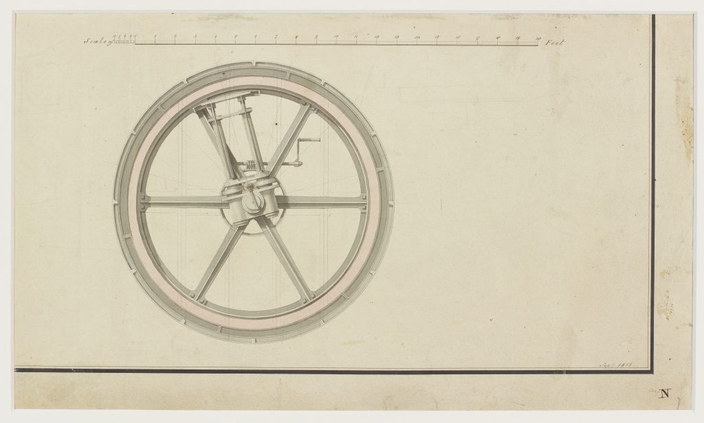
An early watercolour technical illustration depicting two cross sections of an early design for the tunnelling shield. This piece was likely drawn by Joseph Pinchback, Brunel’s chief mechanical draughtsman, and is cut from a sheet dated September 1818. See LDBRU:2017.5 and LDBRU:2017.20 for the complete page and other views of the design.
Brunel’s patent no. 4204 for “Forming tunnels or drifts underground”, published a few months prior on 20 January 1818, described two tunnelling methods. One used a shield made up of several cells driven forward by hydraulic rams. The other, which this design more closely resembles, was inspired by the shipworm and used a centrally-located auger and a circular shield design.
Seen here is the rear end of the tunnel shield. The back of the auger is visible, as is the crank for propelling cast-iron segments into place. There are also scale markings in feet above the drawing.
Compared to the final design used for construction in 1825, this early iteration has a few notable differences. Most obvious is the circular shield, rather than the rectangular one eventually used. The shield is also constructed with only two levels, rather than 3 and the hydraulics system was replaced with a screw-driven design.
Throughout the Industrial Revolution (circa 1750-1900), technical drawings became popular as an effective way of communicating designs and functionality. However, in the early 19th century, engineers began to better understand and appreciate them as a visual medium for shaping public perception and bringing engineering to the masses.
Those intended for the workplace included technical details needed to bring the design to reality. However, pieces like this one differed in that they were created for a more public audience. As presentation pieces, they appealed to the layman through the use of watercolours and directional lighting, which helped the viewer visualise the design, and by omitting any unnecessary and complicating details. These traits, alongside their reproducibility, created a characteristic style that helped bring the industrial world into the public domain.
Brunel was one engineer who used technical illustrations as a promotional tool to grow an audience and publicise designs. For example, this piece dates back to 1818 when Brunel was still planning and campaigning for the tunnel, and it would be another seven years until construction of the tunnel began. These visually appealing watercolours would have played a role in the process of sharing designs and gaining support from several significant investors, as did various illustrations reproduced for pamphlets and publications such as the Mechanics Magazine.
Over time, technical drawings and illustrations began to play a more prominent role in early 19th century engineering, and draughtsmen soon solidified their specialist role in the industry distinct from architects, designers, and engineers. In fact, at the same time Brunel was awarded a silver Telford medal in 1838 for his design and communication of the tunnelling shield, Pinchback was given a bronze medal recognising the “beauty of the drawings.”
If you’d like a print of the artwork displayed above, you can purchase one from the ArtUK online shop.